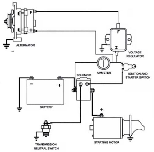
1volt Starter Motor Wiring Diagram
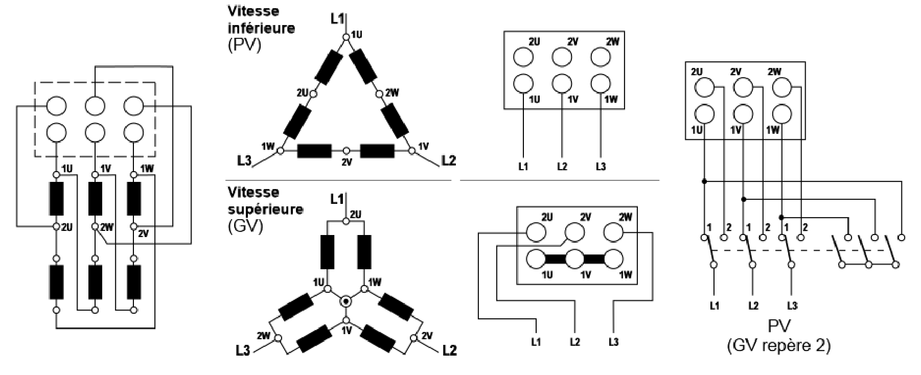
Arduino Based Dahlander Switch Details Hackaday Io
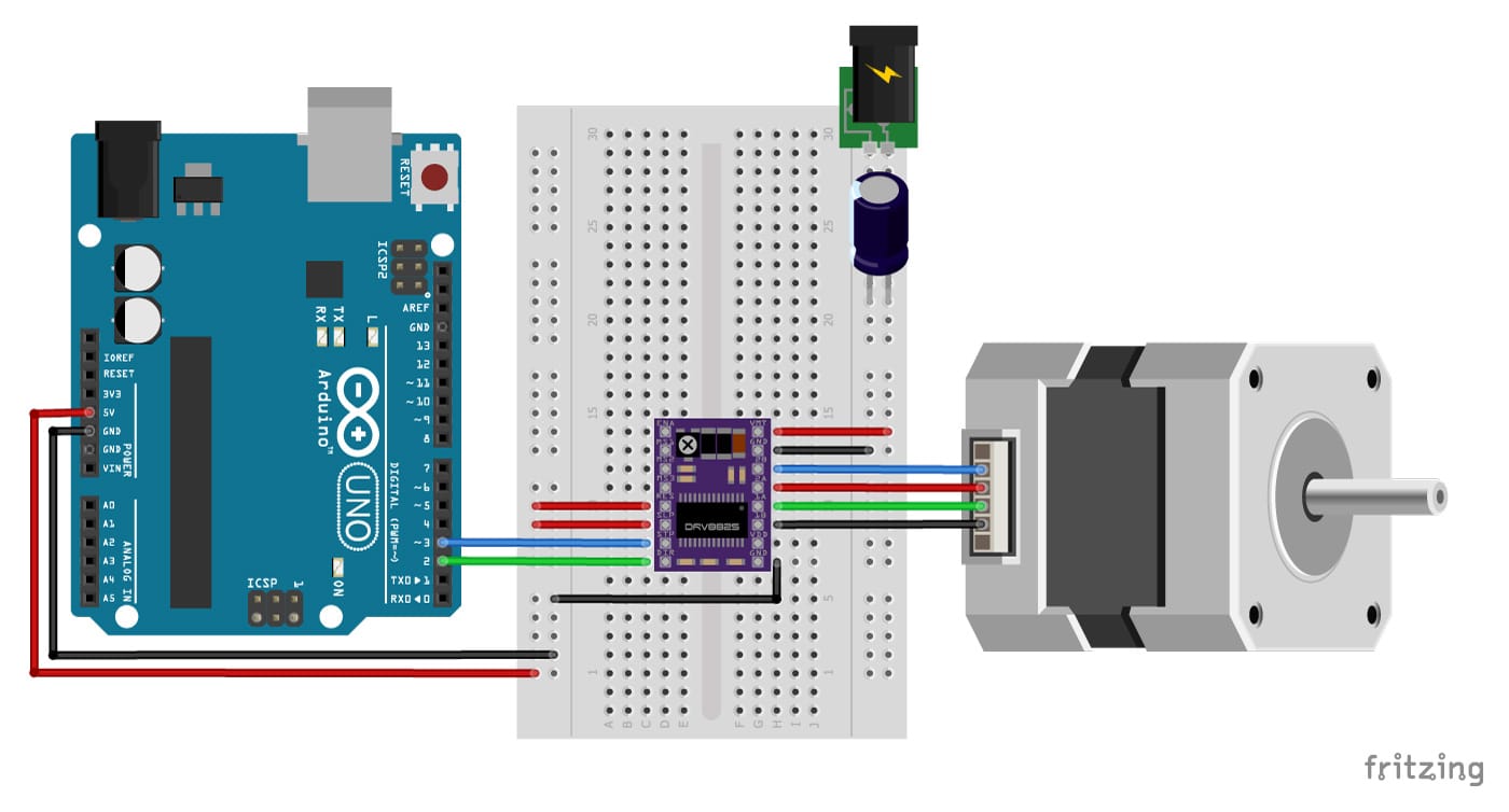
Stepper Motor With Drv8825 And Arduino Tutorial 4 Examples

10 Engine Wiring Diagram Engine Diagram Wiringg Net Electrical Diagram Bmw Bmw Z4
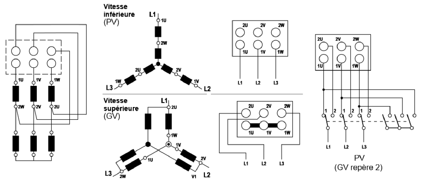
Arduino Based Dahlander Switch Details Hackaday Io
Ignition Coil Alternator Starter Manufacturer Ribo Auto Parts
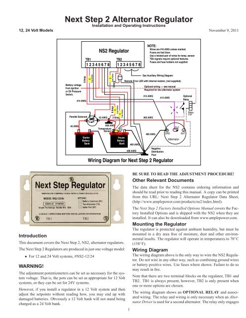
Next Step 2 Alternator Regulator Ample Power

There will be primary lines which are represented by L1 L2 L3 and so on.
1volt starter motor wiring diagram. These instructions will likely be easy to grasp and implement. Magnetic starter wiring diagrams for. Colours can also be used to differentiate wires.
It will also serve as a useful aid where simple wiring systems are to be studied. Motor Starter Visual Paradigm Online VP Online is an online drawing software that supports Wiring Diagram and a wide range of diagrams that covers UML ERD Organization Chart and more. How can you have two different voltages going into the same starter.
When applying these diagrams it is well to remember that the features described in several diagrams may be. Improper wiring can Kill Injure Start Fires Burn Out Motors or anyall of the above. Typical Starter Wiring Diagram Three-Phase Separate voltages supplied by different voltage sources.
C 2015 ENGINE GROUND CABLE STEEL CHASSIS STARTER GM 2 2 516. Starting control circuit with starter relay. 1 22kW motor with a FLC of 5 Amps 415Volts.
Injunction of two wires is generally indicated by black dot to the intersection of two lines. But it doesnt imply link between the cables. A2 - 14 - 18.
A wiring diagram gives the necessary information for actually wiring-up a group of control devices or for physically tracing. L The schematic or line diagram includes all the components. One to three NC overload contacts are shown because starters may include one two or three overload contacts depending on the manufacturer and motor.

Sw Em 123gt Charging System Notes

Training Manual
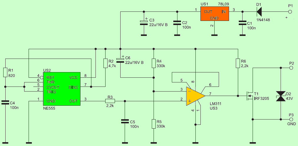
Soft Start Circuit For Dc Motors Electronics Projects Circuits
Https Download Sew Eurodrive Com Download Pdf 9pd0048 Pdf

4 Wire Stepper Motor Wiring Diagram Wiring Diagram Schemas

V8note320 Starter Motor Modification V8 Workshop Notes Template V8 Register Mg Car Club

22 Stunning Electrical Switch Wiring Diagram Bacamajalah Electrical Switch Wiring Electric Cooling Fan Electrical Switches

Pulse Motor And Two Transistor Circuit Youtube Circuit Transistors Circuit Diagram
Sw Em 123gt Charging System Notes
Alternator Wiring From Scratch Rx7club Com Mazda Rx7 Forum
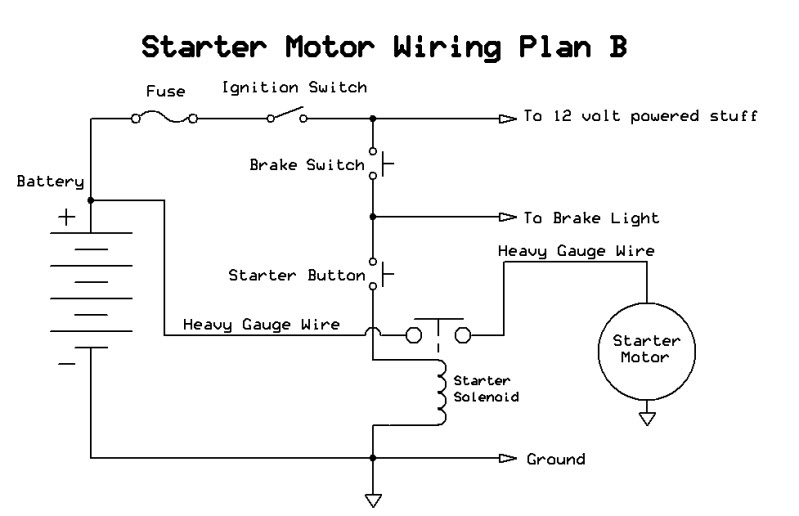
How To Wire A Push Button Starter Atvconnection Com Atv Enthusiast Community
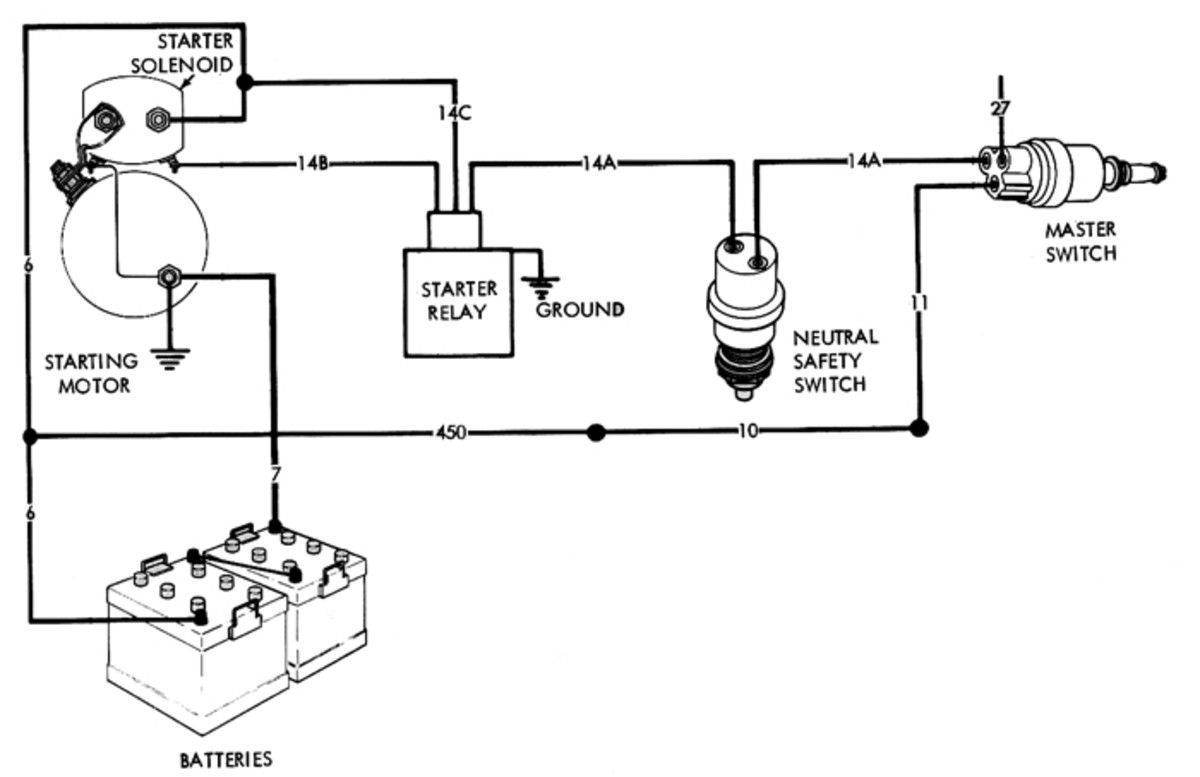
Mv Starter Circuits Military Trader Vehicles

1 5v To 5v Voltage Converter Circuit
