4 Wire Inte Diagram

4 Wire Fan Heater Pin Out Diagram Laptop Fan Electronic Schematics Wire

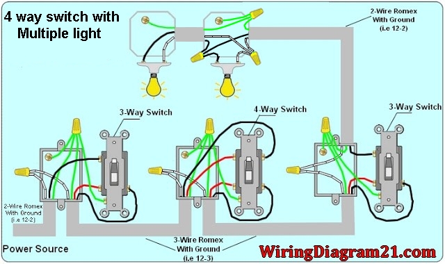
Pin On Electronic Schematics

4 Wire Ignition Switch Diagram Atv New Excellent Chinese Cdi Wiring Best Of Kill Switch Electrical Diagram Electrical Wiring Diagram

Beautiful Wiring Diagram Kancil 660 Diagrams Digramssample Diagramimages Wiringdiagramsample Wiringdiagram Toyota Mitsubishi Lancer Dodge

4 Wire Pressure Transducer Wiring Diagram Transducer Diagram Pressure

4 Wire Alternator Wiring Diagram Instalacion Electrica Electricidad Industrial Instalacion Electrica

I have searched diagrams for it and it seems like it is hooked up correctly.
4 wire inte diagram. Please note the 5th pin is not as standard as the first 4. 18022015 One solution is called the Kelvin or 4-wire resistance measurement method. This 4 way switch diagram 1 shows the power source starting at the left 3-way switch.
Because we now use four lead wires instead of two we refer to this approach as 4-wire measurement or alternatively 4-Wire. If you do this connect the blue wire to the reverse lights on the vehicle side then be sure to note what youve done Better yet use a purple wire and label it. The schematic diagram below shows the wire transmitter configuration.
My input for can be between 5-24v I have attempted to probe the output voltage with a meter and get 1v. 06012020 I have a question on wiring a 4-wire rotary encoder. I cannot find a lot of information about the output voltage.
The voltage dropped across the resistance is measured by the voltmeter and resistance calculated using. A practical schematic of the 4-wire measurement diagram from earlier would look something like the below picture with wire and connection resistances Rw added. The 4 mA zero-end current is sufficient to drive the internal circuitry of the transmitter and the current from 4 to 20 mA represents the range of the measured process variable.
This 4 way switch diagram 2 shows the power source starting at the fixture. The fourth wire if present is provided as a neutral and is normally grounded. On the vehicle side.
Refer to the figure below. At SW1 its spliced to the white wire running to the 4 way switch box where its spliced to the white wire. Connect the wires of the 4-wire trunk connector to the vehicle wiring.

Zoom In Real Dimensions 800 X 533

Diagrama De Cableado Gy6 Lovely Excellent 4 Pin Cdi Ideas Para Diagrama De Instalacion Electrica Electrica Montajes Electricos

26 Chevy 4 Wire Alternator Wiring Diagram Colorado In 2021 Electrical Diagram Voltage Regulator Alternator

4 Channel Amp Wiring Schematic And Wiring Diagram 4 Channel Amp Install Car Audio Installation

4 Wire Ignition Switch Diagram Atv In 2021 Atv Diagram 250cc

12v Relay Wiring Diagram 5 Pin Electrical Circuit Diagram Electrical Diagram Relay
Dimmable Ballast Wiring Diagram In 2021 Ceiling Fan Wiring Ceiling Fan Switch Fan Light Switch
Energy Harvesting Applications Four Way Light Switch Diagram

The Electrical Wiring Diagrams For Ramps 1 4 Reference From Reprap Org Download Scientific Diagram

Magnetic Contactor Connection Diagram Magnetic Contactor Connection Diagram With Electrical Circuit Diagram Electrical Wiring Diagram Basic Electrical Wiring

Wiring Electric Hob Diagram Home Wiring Diagram

Viper 5706 Wiring Diagram In 2021 Home Security Systems Wireless Home Security Systems Alarm System

Amplifier Wiring Diagrams How To Add An Amplifier To Your Car Audio System Subwoofer Wiring Car Audio Systems Car Amplifier
