Inverter Connection Dikhaye

Imaginative Connection Wiring Diagram 1 House Wiring Electrical Circuit Diagram Circuit Diagram

Inverter Ki Wiring Kaise Karte Hain Youtube

Ups Inverter Wiring Diagram For One Room Office Electrical Online 4u Electrical Tutorials House Wiring Circuit Diagram Electrical Wiring Diagram


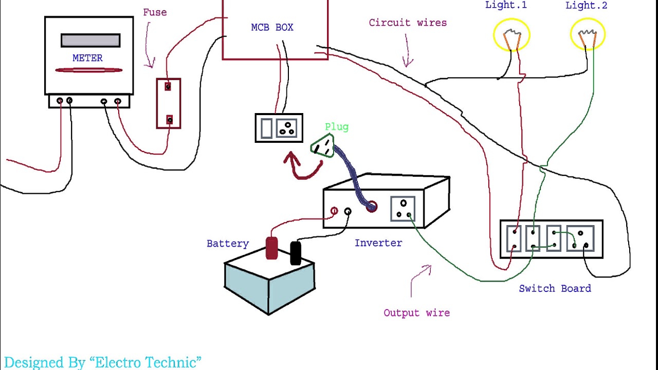
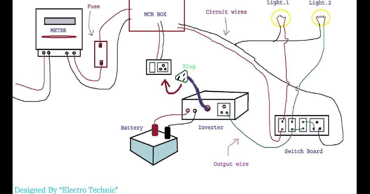
The inverter will now convert the batteries DC current to AC current.
Inverter connection dikhaye. This demonstration presents a three-phase T-type inverter for grid-tie applications that deploys Wolf-speed SiC MOSFETs. The 60 watt bulb should immediately light up brightly indicating that the inverter is functioning properly. The control design of this type of inverter may be challenging as several algorithms are required to run the inverter.
Connect the Battery Banks to the Inverter. Inverters are connected to PV modules. The solar inverter used to convert DC power into AC power.
It shows how the electrical wires are interconnected and can also show where fixtures and components may be connected to the system. 19062018 For testing purpose connect a 60 watt incandescent bulb to the output socket of the inverter. 15082020 Connection to your DB all depends on the space available within your current DB.
This reference design uses the C2000. For example two units are connected in parallel and set SOL in output source priority. Next connect a fully charged 12 V automobile battery to its supply terminals.
Fig1shows the electrical circuit of the T-type inverter. 06112020 The connection of PLC and RS-485 communication interface. By leveraging analysis tools and simulation scripts the inverter.
During grid connected mode grid controls the amplitude and frequency of the PV inverter output voltage and the inverter operates in a current controlled mode. After that attach the battery bank to the inverters input lugs. Then attach the inverter to the house panel and verify that it performs properly.
Inverter Connection Kaise Kiya Home Wiring Diagram

Carrier Window Ac Wiring Diagram Ac Wiring Electrical Circuit Diagram Ac Capacitor

Automatic Voltage Stabilizer Circuit Diagram Circuit Diagram Circuit Diagram
Motorcycle Battery Charger Schematic Battery Charger Motorcycle Battery Electronic Circuit Projects

Simple Inverter Circuit Diagram Electrical Blog Elektrotechnik Elektroniken Schaltplan

Pin On Electrical Technology

How To Connect Automatic Ups Inverter To The Home Supply System Ups System House Wiring Home Electrical Wiring

Manual Auto Ups Inverter Wiring Diagram With Changeover Switch Electrical Circuit Diagram Electrical Wiring Diagram Electrical Diagram

Inverter Connection For Home Youtube

50 Best Of Compressor Start Relay Wiring Diagram Circuit Diagram Ac Capacitor Refrigerator Compressor

Pin On Homemade

Manual Auto Ups Inverter Wiring Diagram With Changeover Switch Transfer Switch Electrical Circuit Diagram Home Electrical Wiring

15 Car Power Inverter Wiring Diagram Car Diagram Wiringg Net Power Inverter Circuit Diagram Inverter Generator
